Introduction to the toughness and fracture mechanics of materials
- First, low stress brittle fracture and material toughness
In the analysis of the brittle fracture of the ship, the brittle fracture of the seamless gas pipeline, the brittle fracture of the iron bridge, the crash of the aircraft due to brittle fracture, and the major accidents caused by the brittle fracture of oil and power station equipment, some were found. Their common characteristics:
1. The macroscopic stress usually occurs when the brittle fracture occurs, and it is safe to design according to the strength;2. Brittle fracture accidents usually occur in relatively low operating temperature environments;
3. Brittle fracture starts from the stress concentration, and the crack source is usually at the defect of structure or material, such as notch, crack, inclusion, etc.4. Thick section and high strain rate promote brittle fracture.
As a result, people have found that the traditional design ideas and material performance indicators are insufficient in strength design, trying to propose new performance indicators and safety criteria, and find new design methods to prevent brittle fracture.The traditional strength design is based on the elastic modulus E, the yield limit σs, and the tensile strength σb, while the plastic index elongation δ and the surface shrinkage φ are only reference data in the design, and the stress concentration is usually considered. Even so, the safety criteria of the design are not enough to prevent the occurrence of brittle fracture, which indicates that the strength, plasticity and elasticity of the material can not fully reflect the ability of the material to resist brittle fracture. After analyzing and researching many brittle fracture accidents, a new performance index, toughness, which is easy to reflect the material's ability to resist brittle fracture, has been proposed. The definition of toughness is derived from the difference in energy consumed to break brittle materials and ductile materials. The so-called toughness is that the energy absorbed by the material from deformation to fracture is too small, which is a comprehensive reflection of material strength and plasticity.
For example, Figure l-2 shows the tensile curves of ductile iron and low carbon steel. The area under the tensile curve can be used to indicate the toughness of the material.

It can be seen that although the tensile strength σb of ductile iron is higher than that of low carbon steel, the plastic strain εp at the time of fracture is much lower than that of carbon steel. In general, the toughness of low carbon steel is high.
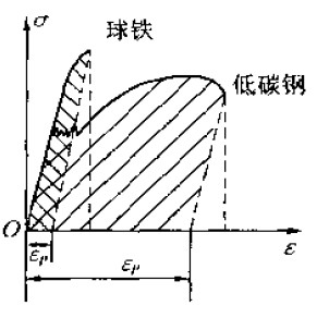 Figure 1-2 Toughness expressed by the tensile curve of ductile iron and low carbon steel
The toughness of the material can be tested and determined experimentally. The earlier and more widely used is the notched impact test, which has been standardized. The specific method is to apply the impact load to the notched sample shown in FIG. 1-3 by a special impact testing machine to break the sample, and divide the work absorbed during the impact by the fracture area, and the obtained product is the impact toughness of the material, with αk Indicates that the unit is J/cm^2. At present, the Xia V-notch specimen is often used internationally, and the u-notch specimen is used in China. Since the notch impact test can accurately determine the toughness of the material and is simple and easy to implement, it is still widely used. The impact toughness of the material in the design is a reference data, and the requirements for the impact toughness value of the material are determined empirically.
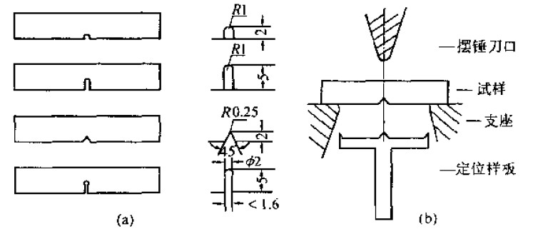 Figure 1-3 transverse impact test(a) Impact specimen (sample size 10×10×55mm^3) (b) Impact specimen placement
Practice has proved that the ambient temperature has a significant effect on the toughness of the material. As the temperature decreases, the toughness of the material will decrease. When the temperature drops to a certain value τT, the impact toughness value will be greatly reduced and the material becomes brittle. In the United States, brittle fracture accidents occur in the lower temperature environment of -10 to 15 °C. Therefore, the brittle transition temperature τt of the material is used as a safety criterion for preventing brittle fracture. The design is based on the operating temperature of the structure. A material having a suitable embrittlement temperature τt to ensure that the operating temperature is higher than the embrittlement temperature to prevent brittle fracture. The standard method for determining the brittle transition temperature τt of a material is now the drop weight test. As shown in Figure 1-4, a small solder ball is deposited in the center of a plate-shaped sample with a thickness of more than 16 mm boron, and a notch is formed on the solder ball. The notch does not damage the mother board, and the sample is placed in the test shown in the figure. On the device, the center of the test piece was freely dropped from a height of 4 to 14 feet with a weight of 60 to 100 pounds. The brittle transformation temperature τt of the material can be measured by testing in a series of different temperature conditions.
The impact toughness αk or the brittle transition temperature τt is used as the toughness index. It is convenient to study the influence of the hot working process of steel on the toughness of the material. However, in the design, these indexes cannot be used to calculate the load when the brittle fracture occurs, but only Can be used as a qualitative reference.In order to directly apply the toughness index of the material in the design, people also use the knowledge of mechanics to analyze the relationship between the brittle fracture problem and the fracture toughness of the material, and study the mechanical parameters reflecting the occurrence and development of the brittle fracture crack. Based on a large number of experiments, the cracked material is applied. The fracture toughness has been studied deeply. The crack propagation, failure and crack arrest of cracked members under various working conditions are explored. The criteria for engineering design are established and a new branch of mechanics is formed. Mechanics.
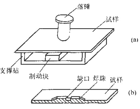 Figure 1-4 Schematic diagram of the drop hammer test method(a) schematic diagram of the device; (b) beads and slits on the reverse side of the specimen2. Introduction to fracture mechanics
Fracture mechanics is a new branch of mechanics with a cracked body as the research object. It mainly studies the conditions and mechanism of crack initiation and expansion. The mechanical parameters and determination methods for determining the actual strength of the cracked material are discussed, and the ways to prevent brittle fracture of the member are discussed. Nowadays, great progress has been made in the study of fracture mechanics, especially the linear elastic fracture mechanics has achieved many mature results. The elastoplastic fracture mechanics is becoming the main direction of scientific research workers in this field. But there are still quite a few problems in many areas that require further efforts. This section only introduces some basic concepts related to fracture mechanics and important fracture mechanics conclusions obtained from fracture analysis.
(1) Relationship between crack size and fracture strengthAn important empirical result when studying fracture behavior is that the magnitude of the nominal stress at the time of fracture of the component is related to the size and shape of the crack inside the structure. For example, using a high-strength material specimen with surface cracks of different depths as a tensile test, the relationship between the crack depth a and the actual fracture strength as shown in Figure 1-5 can be obtained, and the square root of the fracture stress and crack depth is proved. Inverse ratio
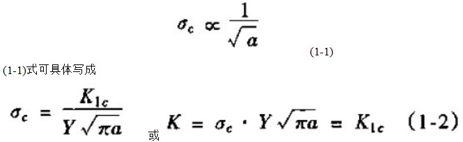
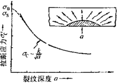 Figure 1-5 Relationship between fracture strength and crack depth
Where σc is the fracture stress, called residual strength: a is the crack depth; 丫 is the shape factor, which is related to the sample geometry, load condition and crack position; K1c is a constant, which is a physical parameter reflecting the material's resistance to brittle fracture. It is called the fracture toughness of the material.
It can be known from (1-2):1. Corresponding to a certain crack size a, there is a critical stress value σc, and the crack only expands when the stress caused by external action is greater than the critical stress. Causes a break. Below this value, the crack will be stable and will not expand. In other words, it corresponds to a certain stress value. There is a critical crack depth ac, that is, ac = K21c / Y2 · π σ2 When the crack depth is less than this value, the crack is stable.
2. The deeper the crack, the lower the critical fracture stress of the material, or the greater the stress acting on the specimen, the smaller the critical dimension of the crack.The above conclusions indicate that the cracked member is safe as long as the crack does not reach the critical dimension or the crack size is constant, as long as the stress is not greater than the critical stress. Thus, considering the existence of cracks, the fracture stress obtained according to the crack instability condition is not necessarily the same as that obtained by the conventional strength conditions. For example, some materials are "higher, but their fracture toughness K1c is very low, while some materials have lower σs, σb, but their fracture toughness K1c is very high. Under the same crack depth, the latter The material can withstand the fracture stress higher than the former. Therefore, from this new point of view, blindly chasing the ball of high-strength material does not necessarily guarantee safety and reliability, and having sufficient fracture toughness is the basis for preventing brittle fracture. Guarantee.
(2) Stress field strength analysis and fracture toughnessSince the quantitative expression of the fracture theory of cracked glass by Griffith in the 1920s, many mechanics have done a lot of work on fracture mechanics, especially the application of elastic theory to the crack frontal stress-strain field by William and Irwin in the 1950s. The analysis has been carried out to improve the linear elastic fracture mechanics and has been widely used in crack design and failure analysis.
In order to analyze the crack tip stress, three basic stress fields are defined, each of which is related to the special way of crack deformation. As shown in Figure 1-6.Type I is a crack open type, in which case the two surfaces of the crack are directly separated, and the type II is an edge slip type or a forward slip type. It appears that the two surfaces of the crack slide toward each other perpendicular to the leading edge of the crack. Type III is a lateral slip type or a tear type, also known as a parallel shear type, which is characterized in that the two crack surfaces slide toward each other in a direction parallel to the crack leading edge. If these three basic types are superimposed, the most general three-dimensional case of local crack tip deformation and stress field can be completely described. The most dangerous and common of the three basic types is the type I open crack. So we focus on the type I crack problem:
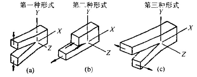 Figure 1-6 Three displacement forms of the crack surface
(1) Analysis of stress and displacement at the crack tip and the concept of stress intensity factor:
An infinite plate is provided, which has a central penetration crack of length 2a, which is subjected to biaxial tensile stress, as shown in Fig. l-7. Solving the plane problem of elastic mechanics, the stress field near the crack tip is
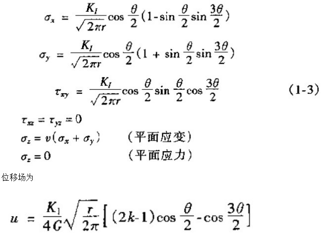
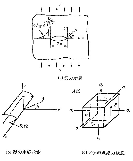 Figure 1-7 Crack front stress field
By (1-3). It can be seen from (1-4) that the distribution of stress and displacement at the front end of the crack is determined only by K1 and coordinates (r, θ). When K1 is determined, the stress field and displacement field at the crack tip are completely different regardless of the change of σ and α. The same, so K1 is an important mechanical parameter that characterizes the strength of the stress field at the crack tip, called the stress intensity factor, and the foot I indicates the case of the type I crack.
The general expression of the stress intensity factor for a cracked body with different stresses and different geometric factors is

Where y is the shape factor determined by the geometrical factors of the crack body. The Y values ​​under various conditions have been formulated and compiled into the Stress Field Intensity Factor Handbook, while Figure 1-8 lists the shape factor expressions in the stress intensity factors for several common shapes.
The dimension of the direct force intensity factor is KN·mm-3/2The shape of the test piece and the crack are different, and the expression of K1 is different. For the infinite plate penetration crack shown in Fig. 1-7, the result of the elastic theory calculation is
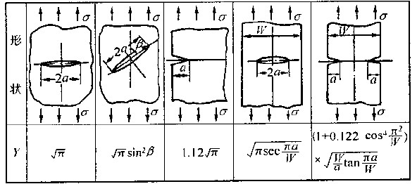 Figure 1-8 Common penetration crack forms and shape factors
It can be seen from Fig. 1-9 that the plastic zone in the case of plane strain is much smaller than the plane stress. This is because, in the plane strain state, the αz generated by the constraint in the thickness direction is the tensile stress, and in the state of the three-direction tensile stress, the material is not easily yielded and becomes brittle.
For thicker plates, the central portion of the thickness is constrained by the Z direction and is in a plane strain state. From the center outward, the constraint is gradually reduced, thus transitioning to a flat and stress state, and the constraint is extremely small when approaching the surface. Has approached the plane stress state.Therefore, the plastic zone at the center of the crack at the crack front of the thick plate is small, and the closer to the surface, the larger. The changes are shown in Figure l-10. The resulting fracture is a slanted fracture at the adjacent surface and a flat fracture at the center. When the K1c of the material is determined by the test method, the thickness of the test must be a certain size to ensure that the entire test is carried out under plane strain conditions, and a positive fracture type is obtained.
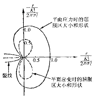 Figure 1-9 The size and shape of the plastic zone at the crack front
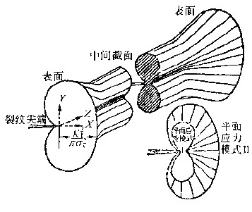 Figure 1-10 Case where the plastic zone size changes along the thickness direction (penetrating crack)
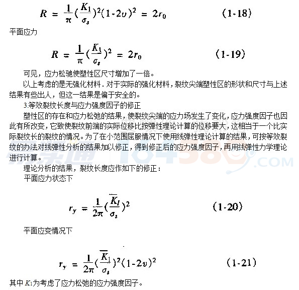
2. The correction of the stress relaxation takes into account the stress relaxation caused by the plastic deformation in the plastic zone, which will enlarge the plastic zone. The analysis results consider that the plastic zone size obtained after stress relaxation is

4. Introduction to elastoplastic fracture mechanics and COD criteria
The linear elastic fracture mechanics introduced in the previous section can only be applied to small-scale yielding problems, and it is effective for high-strength materials. However, in engineering practice, the crack tip in a member or structure made of medium and low-strength materials will undergo large-scale yielding or full yielding, and the plastic zone size can reach the same order of magnitude as the crack length. The fracture occurs at a time close to the yield stress. In this case, the conclusion of the linear elastic fracture mechanics is no longer applicable even if the plastic zone correction is made.The fracture process of elastoplastic fracture and brittle fracture is different. After the crack is cracked, there will be a period of subcritical expansion. When the length reaches a certain length, the instability and fracture will occur. See the solid 1-11(b) describing the crack propagation process. There is no obvious subcriticality for the brittle fracture. During the expansion phase, crack cracking and instability occur almost simultaneously, as shown in Figure 1-11(a).
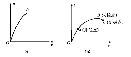 Figure 1-11 (a) brittle fracture Ï-ν diagram, (b) elastoplastic fracture Ï-ν diagram
The fracture shape characteristics of the two fractures are also different and will be discussed in detail later.
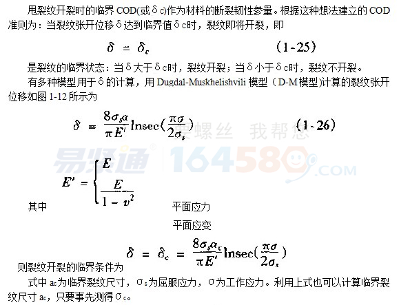
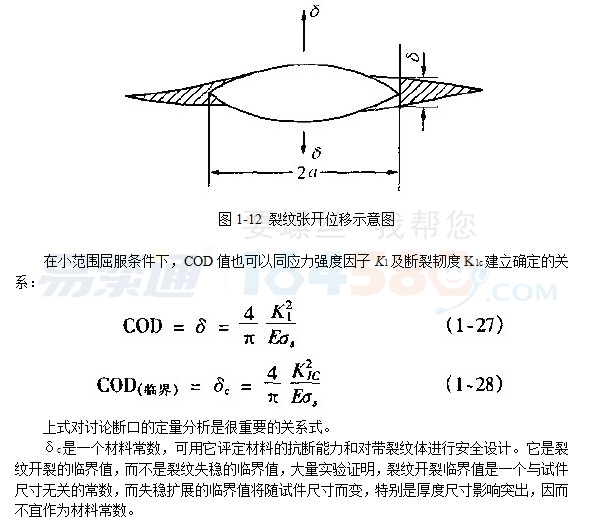
It is difficult to study the stress and strain field of the elastoplastic crack tip in a small range. The fracture toughness parameter is used to describe the law of elastoplastic fracture. Establishing a simple and applicable fracture criterion is a difficult problem that is still being explored. The elastoplastic fracture mechanics of the large-scale yield problem of cracked bodies with elastoplastic theory is only thirty years old. Nowadays, the more mature and widely used elastoplastic fracture criteria mainly include COD criterion and J integral criterion. Crack cracking is used as a critical condition, in addition to the R resistance curve method and the nonlinear fracture toughness G method, which are based on the crack tip instability as a critical condition. This book is not able to describe these details in detail, only a brief introduction to the COD guidelines.The basic concept of the COD criterion is that the fracture behavior of the crack tip can be indirectly described by the Crack Opening Displacement (COD).
We are a professional manufacturer of hydraulic accessories for crawler excavators Professionally provided aftermarket customers with various brands of crawler Excavator Final Drive, Travel Motor , Travel Gearbox, Swing Device , Swing Motor , Swing Gearbox ,Hydraulic Pump, Main Control Valve and other accessories.Strictly controlling the quality acceptance of each product Standards to ensure high-quality qualified export of each product.At the same time, we can customize the production services of the products through the drawings according to customer needs, and make every effort to make the perfect product in the mind of each customer.
If you want to know more about our products in more detail, please click on the product details to see more information about product quality, price, packaging, transportation, etc., or you can directly click on Contact Now on the page to talk to us directly. Looking forward to starting long-term business cooperation with you!
Cab Parts
Cab Parts,Excavator Parts,Crawler Excavator Spare Parts
Jining Juheng Hydraulic Machinery Co., Ltd. , https://www.juheng-cn.com