Numerical Simulation of Filling and Solidification Process of Castings
| 1 Overview In order to obtain a sound casting, a reasonable set of process parameters must be determined. The purpose of numerical simulation or numerical test is to analyze the influence of process parameters on the process implementation results by numerical calculation of the filling and solidification process of castings, so that technicians can verify and optimize the designed casting process and seek process problems. As soon as possible. The calculation of filling and solidification process of castings is based on castings and castings, including numerical calculation of flow and heat transfer of molten metal, mainly used for liquid metal filling and casting process; numerical calculation of heat transfer process of casting castings, mainly used for casting solidification Process; numerical calculation of stress and strain, used in casting solidification and cooling process; crystal nucleation and growth numerical calculation, mainly used for microstructure formation of metal castings and prediction of mechanical properties of castings; numerical calculation of heat and mass transfer capacity, mainly used For the solidification process of large castings or castings with a long solidification time. The predictable defects in numerical calculation are mainly the cold separation, entrainment, shrinkage, shrinkage, crack, segregation, coarse grain, etc. which are easy to occur during the formation of castings. In addition, reasonable casting process parameters can be proposed through numerical calculation. Including casting temperature, mold temperature, casting solidification time, boxing time, cooling conditions, and so on. At present, the numerical calculation of the flow and heat transfer of molten metal used in the liquid metal filling and casting process and the numerical calculation of the heat transfer process of the casting mold used in the solidification process of the casting have been relatively mature, and are gradually adopted by the foundry in actual production. Introduce these two numerical test methods. 1.1 Mathematical model The molten metal filling and solidification process is a high temperature fluid in the complex geometry cavity with obstruction and free surface flow and heat transfer to the mold and air. The physical process follows the laws of mass conservation, momentum conservation and energy conservation. Assuming that the liquid metal is a viscous fluid with a constant density and is incompressible, and ignoring the turbulence, the process can be described by continuous, momentum, volume function and energy equations.
1.2 Solid modeling and meshing 1.3 Numerical calculation method There are three main methods for numerical calculation of casting filling and solidification process: finite difference method, controlled volume method (also known as finite volume method) and finite element method. The latter two methods are used less and are currently popularized in the foundry market. Most of the numerical simulation software uses the finite difference method. Taking the finite difference method as an example, the discretization of equation (2-1) uses the central difference method, and the discrete equations (2-2) and (2-4) use the combination of the upwind scheme and the central difference scheme. The free surface of the liquid metal during the filling process is constantly changing, and the calculation domains corresponding to each time step are different. The determination of the new calculation domain is obtained by solving equation (2-3). The ordinary numerical method will cause a large false diffusion problem in the discrete equation (2-3), and the result will be Smearing. There are a large number of free surface elements between F =1 and F =0. In order to obtain a clear free surface, researchers in the United States have developed a VOF (Volume of Fluid) method that better handles the free surface calculation of fluid flow processes. At present, in the field of computational fluid dynamics, some more accurate methods have been developed on the basis of the VOF method, and a more accurate free surface variation of the fluid flow process can be obtained. The numerical calculation steps of the filling and solidification process are as follows: 1) Casting and casting as the calculation domain for solid modeling, splitting and unit identification. 2) Give initial conditions, boundary conditions, and physical properties of metals and molds. 3) Solving the volume function equation to obtain the fluid flow calculation domain at a new time. 4) Solving the continuity equation and the momentum equation, and obtaining the velocity field and pressure field of the fluid in the calculation domain at the new time. 5) Solve the energy equation to obtain the temperature field of the casting and the mold and the solid phase fraction of the liquid metal. 6) Add a time step and repeat steps 3) to 6) until the filling is completed. 7) Calculate the fluid flow velocity in the domain to zero and adjust the time step. 8) The temperature field of the casting and the mold calculated at the completion of filling is taken as the initial temperature condition, and the energy equation is solved until the casting is solidified. 9) Post-processing of calculation results, analysis of casting process, prediction of casting defects and optimization of process parameters. 1.4 Application examples An example of optimizing the casting process parameters of low pressure cast aluminum alloy wheel castings using ZCAST software is given below. In the low-pressure casting process of the hub casting, automatic control of the mold temperature is important to prevent shrinkage shrinkage defects, coarse structure and prolonged production cycle. Simulation calculations and water-cooled controllers can be an important tool in metal mold design. A reasonable cooling system is designed by simulating the flow and solidification of the hub casting during the cycle. Control the heat dissipation or accumulation of the mold by using a water-cooled controller. Productivity can be increased by reducing cycle times and casting defects on the foundry's low pressure casting wheel casting line. The simulation calculation steps are shown in Figure 2-1. First, the pre-processing is performed. The main work of the pre-processing is to calculate the 3-dimensional solid shape of the casting mold in the domain, and then import the solid modeling file into the ZCAST software, and input the calculation boundary conditions, including the inflow boundary, the initial temperature, and the thermocouple position setting.
Figure 2-1 Numerical calculation process After the pre-treatment is completed, the numerical simulation calculation is started, including the combination and opening process in one cycle. The forming process considers filling and solidification, and the opening process only considers the heat transfer of the mold cavity. The numerical simulation calculation section can consider a plurality of cyclic processes in order to observe whether the production process is stable. After the simulation calculation is completed, it is the post-processing process, which is mainly to visually analyze the simulation calculation results and adjust the casting process parameters.
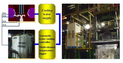
Figure 2-2 Test equipment, TC is the thermocouple position Figure 2-2 shows the test equipment, including the cooling water supply system, multi-channel temperature acquisition system (left), low-pressure casting equipment and mold (right).
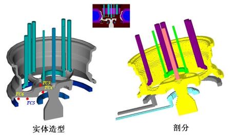
(a) (b) Figure 2-3 Solid modeling and splitting, including solid casting, casting system, casting and cooling channels. TC is the thermocouple position. Figure 2-3(a) shows the result of solid modeling in the calculation domain, and Figure 2-3(b) shows the result of meshing in the calculation domain. Table 2-1 lists the simulation calculation conditions. Interfacial heat transfer coefficient (cal/cm 2 × sec × ° C): 0.03 for casting/casting, 0.004 for casting/air, and 0.1 Pa×s for liquid metal dynamic viscosity. Table 2-1 Physical parameters used in the simulation calculation
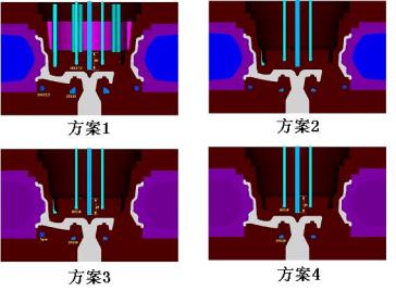
Figure 2-4 Four different process plans Figure 2-4 shows four process options. The differences between the four process options are shown in Table 2-2. Table 2-2 Cooling conditions (Note: time unit s, size unit mm)
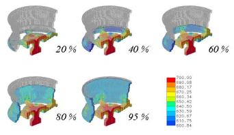
Figure 2-5 Filling process simulation results
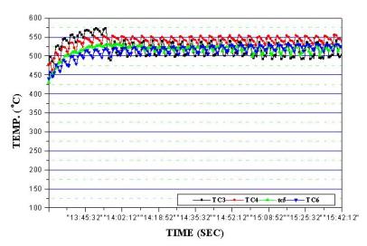
Figure 2-6 Temperature change of the mold-related position Figure 2-5 shows the simulation results of the filling process, from which it can be seen that the filling process is stable. No cold gas gap defects occur. Figure 2-6 shows the calculation of the temperature change of the thermocouple point set on the mold, which is basically consistent with the test results in Figure 2-7.
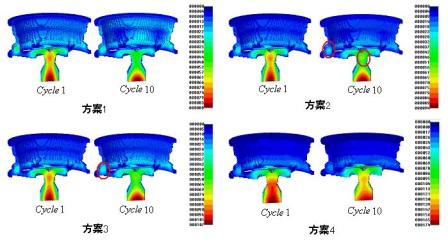
Figure 2-7 Measured temperature change of the relevant position of the mold Figure 2-8 shows the solidification time distribution of each part of the casting obtained by simulation. It can be seen that the first three schemes may have shrinkage or shrinkage defects near the rim, and scheme 4 is ideal. Figure 2-10 demonstrates this. Figure 2-9 shows the temperature change of the mold during the cycle casting process. It can be seen that the temperature distribution of the mold caused by different cooling conditions is different, and some local overheating is obvious as in Schemes 2 and 3.
Figure 2-8 Distribution time of casting solidification
Figure 2-9 Temperature distribution of the mold
Figure 2-10 Comparison of simulation results with test casting results In the hub casting, by analyzing the simulation results of the Z-CAST software, it is possible to obtain optimum cooling and casting conditions for preventing shrinkage defects. According to the numerical simulation results, an automatic water cooling system is used to maintain the semi-steady state of the mold temperature in the periodic metal casting process. After optimization by Z-CAST software, defects due to shrinkage were reduced by 5% and casting productivity was increased by 28%. |


Royal Brick Texture PU Sandwich Panels
Royal Brick Texture PU Sandwich Panels

Rich selection of textures and colors meet different decoration requirements, giving the city and the buildings a new look.
The PU foam is the most advanced and eco-friendly insulation material in the world. With the help of the back aluminum foil, the thermal preservation effect achieves the best.
The unique structure prevents the heat loss in winter. Meanwhile it reduces the heat of the summer sunshine.
Aceta paintcoat and flurocarbon paint of weather resistance performance are applied on surface of wall panel. It is reserved with superior self-cleaning, weather resistance, corrosion resistance and acid& alkali resistance performance.
Light weight with 3.7Kgs/m2 makes the installation easy.
The installation process is clean and tidy without any noise and dust, construction waste.
Different selections of accessories meet different effects.
High quality and stable performance: Manufactured in CNC automation production line, the product pass rate can reach 99.9% with stable chemical structure and physical structure.
Brick Wall Panels,Metal Insulation Decorative Boards,Pu Foam Sandwich Panels,Royal Brick Texture Pu Sandwich Panels
Jinan Zhengtang Insulation Decoration Material Co.Ltd , https://www.ztwallsiding.com