"Emergency retraction" function on the gear shaping machine (Figure)
Our company has undertaken the task of exporting a large-scale CNC gear shaping machine. The user requires the machine to respond quickly to the opposite direction of the machine feed in the case of a sudden power failure of the external power supply to protect the workpiece and The safety of the tool. Therefore, we chose SIEMENS840D numerical control system to realize the electrical control of the machine tool, and use its option function “emergency retreat†to meet the requirements of users. The whole electronic control system was designed and manufactured with the structure of SIEMENS840D numerical control system + 611D drive +1 FT6 motor +1PH7 main motor + 20μF capacitor + S7-300PLC, and it has won the praise of users.
1. Machine basic state and working principle
This machine is a large-sized special tooth cutting machine for straight and helical tooth machining. It can be used for selective cutting of internal and external teeth. The machine tool is driven by the linear feed motion of the table (Y axis), the rotary feed motion of the table (B axis), the rotary feed motion of the tool (C axis), and the up and down reciprocating motion (SP axis) of the pinion cutter axis. The drive components are constructed as shown in Figure 1.
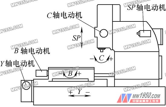
figure 1
(1) Linear feed motion of the table (Y axis) The movement of the axis in this direction is to use the servo motor to drive the precision ball screw through the deceleration system composed of the worm and worm gear to realize the feed or retreat of the table. The speed and feed value are achieved by the movement of the shaft in this direction. The "emergency fallback" function is implemented by this axis.
(2) Rotary feed motion of the table (B axis) The rotary feed of the machine tool workpiece is a continuous motion, which is realized by a servo motor driving the precision reducer to drive the table worm wheel. The rotary feed motion (C axis) of this axis and the tool is a set of linkage axes. When cutting the same workpiece, the linkage relationship between the two axes must be strictly guaranteed.
(3) Rotary feed motion of the tool (C axis) This axis is the tool rotation axis, and the tool holder worm wheel is driven by a servo motor to drive the rotation of the tool.
(4) Up and down reciprocating motion of the pinion cutter shaft SP axis) The bed spindle is driven by a servo spindle motor through the speed reduction mechanism to move the spindle slider up and down. The cutter is connected to the slide through the cutter shaft, and then slides up and down to realize the workpiece. Cutting. The spindle slider and the cutter shaft have a large self-weight. During the process of the cutter shaft falling, the spindle servo motor actually has a small output power, and basically the motor is moving by the rotational inertia of the cutter shaft and the slider. Therefore, we have also taken this into account when designing the "power-off and retreat" function. The energy fed back by the spindle plus the energy stored in the capacitor module drives the linear feed motor (Y-axis) of the table to be powered off. Instantly retreat a short distance in the opposite direction of normal working direction.
2. System hardware configuration
In order to realize the overall cutting performance, machining accuracy and "power-off back-off" function of the machine tool, the following configuration is adopted on the hardware, as shown in Figure 2:
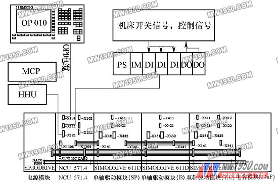
figure 2
Next page
Shangqiu Jinda Tools Co.,Ltd , https://www.jindameasuring.com